How to choose a flatbed trailer deck length for oversized loads
An oversized load can appear to fit on a trailer during an early equipment review, then create problems at the loading point: the boom extends beyond the deck, the center of gravity lands too close to an axle group, or the operator has no practical place to position blocking and tie-downs. The right deck length is not simply the length of the cargo. It is the usable loaded length needed to support the item safely while preserving axle loading, route compliance, securement access, and workable loading geometry.
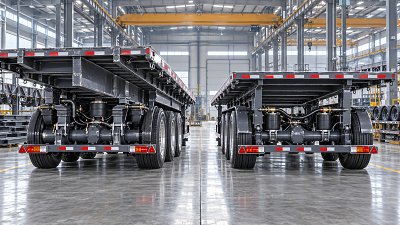
For most project moves, start by selecting a flatbed trailer deck that provides enough clear deck space for the cargo footprint plus the operational space required for load positioning. A longer deck is appropriate when the load has a long supported base, needs separation from other components, requires crane access or special securement, or must be positioned away from the trailer front and rear. A shorter deck may be preferable when the load is compact, weight concentration is the primary concern, and a longer unit would add turning, permit, or routing complications. The correct choice comes from a load-and-route assessment rather than a single overall-length measurement.
Begin with the cargo’s supported length, not its maximum overall length
Project equipment often has appendages that increase overall length without needing full deck support. A machine may have a boom, blade, bucket, counterweight, pipe rack, or structural extension that can legally overhang the deck. Other items must be supported along nearly their entire base because unsupported sections could bend, shift, damage the cargo, or create an unstable load condition.
Separate the cargo dimensions into three measurements before comparing trailers:
- Overall transport length: the longest end-to-end dimension after removable or foldable components have been addressed.
- Supported footprint length: the length that must sit on the deck, blocking, saddles, or purpose-built supports.
- Restricted positioning length: the portion that cannot be placed over a gooseneck, beyond a deck transition, near a tire area, or where tie-down access is blocked.
This distinction prevents a frequent mistake: specifying deck length from an equipment brochure’s overall length. A long excavator boom may be managed as controlled overhang, while a long crawler track assembly needs a continuous bearing surface. Similarly, fabricated modules may have a short structural base but a long upper frame that affects the total load envelope, turning clearance, and permit conditions.
Ask the equipment team for a transport configuration drawing whenever possible. It should show lifting points, support points, axle or track contact locations, removable components, vulnerable projections, and any surfaces that cannot bear weight. A basic outline drawing can still be useful, but it should not replace confirmation of where the cargo can actually be supported.
Allow working space around the load
A deck that exactly matches the supported cargo length is rarely the most workable answer. The load needs room for timber blocking, cribbing, anti-slip material, chains or straps, edge protection, and inspection access. The required margin varies by cargo, but the principle is constant: the operator must be able to secure the load without improvising around trailer edges or inaccessible attachment points.
Front clearance matters when the cargo needs to sit behind the trailer neck, bulkhead, or headboard. A load placed too far forward can interfere with turning clearance between tractor and trailer, especially on designs with a raised front section. Rear clearance matters because it affects overhang, tail swing, ramp use, and the position of warning devices where required.
Consider a long steel structure with lifting lugs located close to each end. Even if its base technically fits within the deck, the trailer may be unsuitable if chains cannot be led at effective angles or if the lugs end up directly above an obstruction. Adding deck length may solve the problem; changing loading orientation, using engineered saddles, or selecting a different trailer configuration may solve it more efficiently. Length should therefore be reviewed together with deck layout, not treated as an isolated specification.
Deck length changes where the weight sits
Project managers sometimes assume that a longer deck always provides more flexibility. It can, but greater length also makes it easier to place a concentrated load in the wrong position. Oversized equipment is often heavy in one area: a counterweight, power unit, gearbox, transformer core, hydraulic pack, or reinforced end section may carry a disproportionate share of total mass. The cargo’s geometric center is not necessarily its center of gravity.
The practical question is not “Will it fit?” but “Where will the weight transfer to the trailer and tractor after it is secured?” The answer depends on cargo position, trailer axle arrangement, deck height, kingpin or hitch location, and the trailer’s rated load distribution. A compact but heavy component may need to be positioned precisely over a specified deck zone. In that case, a longer deck can be useful only if it allows that zone to be reached without creating excessive front or rear projection.
Before committing to a deck length, obtain or estimate:
- Gross cargo weight, including loose accessories transported with it.
- Center-of-gravity location in relation to a known reference point.
- Point loads from tracks, wheels, skids, legs, saddles, or fabricated supports.
- Trailer tare weight and rated capacity for the intended configuration.
- Expected load distribution across the tractor and trailer axle groups.
A transport provider or trailer manufacturer can help model axle loading for a proposed arrangement. This review becomes especially important when moving concentrated loads, modular equipment, or machinery with uneven front-to-rear weight distribution. Do not assume that sliding the load a short distance is harmless; even a small repositioning can affect axle group loads and coupling forces.
Choose length after deciding whether overhang is acceptable
Overhang is not automatically a design failure. Controlled front or rear overhang is often part of oversized transport planning. The important issue is whether the overhang is compatible with the cargo, trailer, route, turning path, and applicable permit conditions.
A long item may be safer on a shorter deck with planned overhang than on an excessively long trailer that is harder to route through site entrances, roundabouts, bridge approaches, or temporary works areas. On the other hand, a longer deck may reduce the total vehicle combination length impact of a particular configuration if it permits a different cargo orientation or avoids a high rear projection. There is no universal “best” amount of deck length.
Route review should happen before trailer selection is finalized, not after the load has been packaged or dispatched. The route may impose limits related to overall combination length, bridge loading, turning radius, lane position, clearances, escort requirements, travel windows, or site-specific access rules. Requirements differ by jurisdiction and route authority, so permitted dimensions and operating conditions must be confirmed for the actual move.
Match deck length to the loading method
The way cargo gets onto the trailer can make a nominally suitable deck impractical. Crane-loaded structures need clear landing zones and sufficient deck area for riggers to remove lifting gear safely. Roll-on equipment requires appropriate ramp geometry, traction, breakover clearance, and load-bearing capacity. Forklift-loaded pallets or skidded assemblies need enough room for approach, placement, and repositioning without forcing workers into unsafe positions.
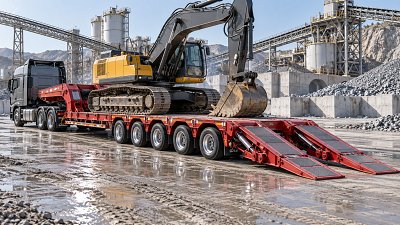
For self-propelled machines, examine more than the final resting length. Measure the approach path from ramp to deck, including the point where tracks or wheels transition onto the trailer. Long wheelbase equipment, low ground clearance, or attachments extending ahead of the machine can strike ramps, the deck edge, or the tractor-trailer connection area. A longer deck does not solve every loading-angle issue, but it can provide the space needed to position the machine after it clears the transition.
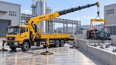
Crane-loaded cargo creates a different constraint. A long deck may give the lift team more placement tolerance, but only when the trailer can be positioned within the crane’s planned working radius and the site has adequate outrigger space. It is better to resolve lifting and trailer-positioning constraints together than to order a longer unit based solely on cargo dimensions.
Look beyond nominal deck length
Trailer specifications can describe overall platform length in ways that obscure usable space. A published deck figure may include sections interrupted by a gooseneck, wheel wells, ramps, a raised deck area, or structural transitions. For oversized loads, confirm the dimensions of the continuous flat loading area and identify any sections with reduced width, reduced height clearance, or limited tie-down points.
Key dimensions to request include:
- Clear main-deck length and width.
- Front deck, rear deck, and any stepped or raised sections.
- Distance from the front of the usable deck to the axle group.
- Deck height when loaded and unloaded.
- Location, rating, and accessibility of lashing points.
- Ramp length, ramp capacity, and ramp stowage impact.
- Space affected by toolboxes, landing gear, headboards, tire carriers, or other fittings.
These details matter when a load has a wide base, low clearance, irregular underside, or securement points close to the cargo ends. A trailer may have enough advertised length yet still fail the practical fit check because a critical support point lands on a transition or because the rear portion of the deck cannot be used as intended.
A practical sizing sequence for project planning
Start the process with the final transport configuration, not the equipment’s operating configuration. Remove, fold, drain, detach, or separately transport components only where the manufacturer’s instructions and project requirements allow it. Then prepare a simple load sheet showing overall dimensions, supported footprint, weight, center of gravity, support points, and prohibited contact areas.
- Define the load envelope. Record transport length, width, height, weight, and any projections that cannot be removed.
- Mark the support zone. Identify exactly where the deck, blocks, saddles, or track pads will carry the load.
- Set the preferred weight position. Use axle-loading information to identify the deck area where the load should sit.
- Add operational clearance. Include space for securement, blocking, loading equipment, and any required protective materials.
- Test overhang options. Compare a longer deck with a shorter deck plus controlled overhang, considering route and site constraints.
- Confirm the actual trailer drawing. Verify usable deck sections, not only the headline trailer length.
- Review the route and site access. Check that the selected configuration can be permitted and physically handled from origin to destination.
This sequence is useful when project details change late. A revised attachment, altered packing method, or additional accessory can move the center of gravity or consume the clearance originally reserved for securement. Updating the load sheet is faster and safer than relying on a previous trailer choice made for a similar-looking machine.
When a longer deck is the wrong answer
More deck length can introduce costs and constraints without improving the move. A longer trailer may be harder to stage on a congested site, less maneuverable at plant entrances, and more difficult to position beside cranes or loading bays. It may also add unnecessary tare weight, reducing the payload margin available for the cargo. Where permits depend on total vehicle configuration, extra length can create route restrictions that a shorter arrangement would avoid.
Do not extend deck length simply to eliminate every inch of overhang. The safer choice may be a trailer that supports the structural base correctly, places the center of gravity in the right zone, and leaves a manageable projection that is addressed through route planning and permit review. Conversely, do not use overhang as a shortcut when it leaves fragile sections unsupported, obstructs lights or warning devices, compromises tie-down angles, or creates unacceptable tail swing.
The final selection should document the proposed cargo position, support method, securement approach, axle-load assessment, loaded dimensions, and route assumptions. That record gives engineering, transport, and site teams the same reference before the equipment reaches the loading area. A flatbed trailer deck length is then being chosen as part of a workable transport configuration, rather than as a single number matched to the cargo’s longest dimension.
Trending News
- When does a light commercial vehicle for urban delivery save fleet costs?
- How to choose an off road truck for steep and unstable job sites
- How to match crane truck lifting capacity to your jobsite loads
- What drives logging truck cost beyond the base purchase price?
- How to match lowbed trailer deck height to your hauling equipment
Tag
Recommended News
 Buying GuideHow to choose an off road truck for steep and unstable job sitesChoose the right off road truck for steep, unstable job sites. Compare traction, braking, stability, clearance, payload, and route-test essentials.
 Buying GuideHow to match crane truck lifting capacity to your jobsite loadsCrane truck capacity planning made clear: calculate gross load, radius, rigging, outriggers, and ground conditions to select safer, job-ready lifting equipment.
 Buying GuideHow to match lowbed trailer deck height to your hauling equipmentLowbed trailer deck height guide: match equipment clearance, ramp geometry, axle loads, tractor fit, and route limits for safer, more efficient hauling.
 Buying GuideWhat to verify before choosing a delivery truck supplier for school transportationDelivery truck supplier for school transportation: verify route fit, payload, safety, compliance, service support, and total cost before choosing a reliable partner.
 Buying GuideWhat an excavator manufacturer catalog should show before you compare modelsExcavator manufacturer catalog guide: verify supplier identity, configurations, hydraulics, compliance, parts support, and delivery readiness before comparing models.
 Buying GuideWhat to check before appointing a bulldozer distributorBulldozer distributor selection guide: evaluate service, parts availability, warranty, pricing, compliance, and lifecycle value to reduce downtime and protect fleet investment.
 Buying GuideWhat to verify before choosing a truck cement mixer supplierTruck cement mixer supplier checklist: verify chassis fit, drum quality, hydraulics, compliance, spare parts, and after-sales support before you buy.
 Buying GuideHow to verify a truck spare parts supplier before placing a bulk orderTruck spare parts supplier verification made practical: learn how to check part specifications, factory control, test records, samples, pricing, and delivery capability before placing a bulk order.
 Buying GuideWhat size truck container is right for a typical freight load?Truck container sizing made simple: compare payload, volume, pallet layouts, route access, and loading needs to choose the most efficient freight solution.
 Buying GuideWhat drives semi trailer price differences between similar models?Semi trailer price differences come down to frame materials, axles, suspension, coating, and configuration. Compare specifications line by line to choose lasting value.
 Buying GuideHow to compare excavator manufacturer price lists before requesting quotesCompare an excavator manufacturer price list with confidence. Learn to normalize configurations, calculate landed costs, assess options and service, and create stronger RFQs.
 Buying GuideHow to choose a mixer truck drum capacity for your concrete pourMixer truck capacity guide: match drum size to pour rate, legal payload, site access, and delivery cycles for efficient, reliable concrete placement.
 Buying GuideHow to size a bulldozer for construction site grading workBulldozer for construction sizing guide: match weight, blade, traction, grade control, and transport needs to improve grading productivity and costs.
 Buying GuideHow to assess a truck cement manufacturer’s build quality before orderingTruck cement manufacturer build quality: assess tank steel, welding, chassis integration, pneumatic systems, factory QC, and inspection evidence before ordering.
 Buying GuideWhen does a truck trailer OEM make sense for private-label fleets?Truck trailer OEM programs help private-label fleets cut lifecycle costs, standardize operations, and improve uptime. Learn when customization delivers real commercial value.
 Buying GuideWhat to verify before choosing a water truck OEM for your fleetWater truck OEM selection guide: verify chassis compatibility, tank quality, pump performance, compliance, and service support to build a safer, more reliable fleet.
 Buying GuideHow to size a cab chassis truck for a fire department apparatusCab chassis truck for fire department sizing guide: balance GVWR, axle loads, wheelbase, water tank placement, and mission needs for safer apparatus design.
 Buying GuideWhat to verify before choosing a truck chassis supplierChoose the right truck chassis supplier with a practical checklist for application fit, axle ratings, body integration, quality control, delivery reliability, and after-sales support.
 Buying GuideHow to choose a logging truck for steep and rough forest roadsLogging truck selection for steep, rough forest roads: compare traction, braking, gearing, chassis strength, tires, and supplier support for safer, more reliable hauling.
 Buying GuideHow to choose a flatbed trailer deck length for oversized loadsFlatbed trailer deck length guide for oversized loads: balance cargo support, axle weight, securement space, overhang, and route access for safer transport.
 Buying GuideHow to assess a truck chassis supplier for trailer manufacturingTruck chassis supplier for trailer manufacturing: learn how to assess technical fit, quality control, engineering support, and delivery reliability for smarter sourcing.
 Buying GuideIs the SHACMAN H3000 6×4 Cement Mixer suitable for large projects?SHACMAN H3000 6×4 Cement Mixer: assess payload, cycle time, traction, and service support to see if it can keep large concrete projects moving efficiently.
 Buying GuideHow to evaluate heavy duty trucks for sale in Russia before buyingHeavy duty trucks for sale in Russia: learn how to compare specifications, winter readiness, service support, supplier reliability, and total ownership costs before buying.
 Buying GuideWhat to verify before choosing a logging truck producerChoose a logging truck producer with confidence: verify chassis strength, load security, compliance, service support, and delivery control for demanding forestry routes.
 Buying GuideHow to choose a truck excavator for confined construction sitesTruck excavator selection for confined sites: explore access, reach, stability, attachments, and safety factors to choose a productive, space-efficient solution.